The diagrams below illustrate the arrangement of components within the system and the major flow paths.
Forced - or Natural Draft Cooling Tower
 | ||||||||||
| The green flow paths show how the
water is taken from a river (yellow) to an intake supply basin (green)
that the Circ Water Pumps take a suction from. The water is then pumped
to the Condenser where the water is heated. The water is then sent to an exit distribution basin where the water then can be returned to the river and/or pumped by the Cooling Tower Pumps to the Cooling Towers then the water returned to the intake supply basin where the water can be reused. |
Natural Draft Cooling Tower
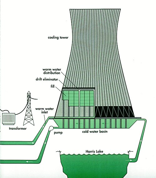 |
| Courtesy CP<he green flow paths show how the warm water leaves the plant proper, is pumped to the natural draft cooling tower and is distributed. The cooled water, including makeup from the lake to account for evaporation losses to the atmosphere, is returned to the condenser. |
Hi friends,
ReplyDeleteNatural draft cooling towers are particularly attractive as a cost-saving solution for larger power stations and industrial plants requiring greater quantities of cooling water. As this type of cooling tower operates without fans, the substantial amount of electric power otherwise required for large cooling tower systems is not needed. Thanks a lot....
Heat Exchanger Cleaning