Tuesday, December 14, 2010

READY MIX CONCRETE

•Ready mix concrete is concrete that is made at ready-mixed plant and then transported to the site in rotating-drum trucks or transit mixers.
•Proportioning, batching, mixing and delivery are all done by the concrete supplier.
•High quality control
•Advantages of using ready mix concrete:
a) better quality concrete due to usage of trained personnel and automated equipment.
b) elimination of material storage on congested building sites- no need to allocate place at site for storage of cement, aggregate, sand
c) save the contractor’s time and usage of labour’s energy to mix the concrete 
•For ready mix concrete supply, the purchaser should specify the following: 
a) Designated max. size of coarse aggregate
b) Desired / max. slump at the point of delivery
c) Air content (for air entrained concrete)
d) Mix design requirement – such as cement content, max. water content & admixtures or minimum compressive strength at 28 days
e) Unit weight required (for structural lightweight concrete).

Imp points abt mixing of concrete

MIXING
•Done in order to ensure each particle of aggregate in fresh concrete will be coated with the cement paste
•Also to give a homogenous even coloured product.
•First stage of mixing is called “BATCHING”.
•Batching is process where it involves weighing out or measuring out all of the ingredients for a batch of concrete.
•The materials that are mixed at any one time constitute a batch.
•Quality of concrete depends on the accuracy of the batching operation.
•However, thorough mixing is essential for complete blending of the materials that are required for the production of homogeneous, uniform concrete.
•Inadequate mixing result in lower strength.
•There are 2 method for concrete mixing that is:  
    a) hand mixing
    b) machine mixing
•The biggest problem with concrete produced with construction mixers on site is quality control.

Thursday, October 28, 2010

Geotechnical design methods for piles

In order to separate their behavioural responses to applied pile load, soils are classified as either granular/noncohesive or clays/cohesive. The generic formulae used to predict soil resistance to pile load include empirical modifying factors which can be adjusted according to previous engineering experience of the influence on the accuracy of predictions of changes in soil type and other factors such as the time delay before load testing.

 The load settlement response is composed of two separate components, the linear elastic shaft friction Rs and non-linear base resistance Rb. The concept of the separate evaluation of shaft friction and base resistance forms the bases of "static or soil mechanics" calculation of pile carrying capacity. The basic equations to be used for this are written as:

Q = Qb + Qs - Wp or
Rc = Rb + Rs - Wp
Rt = Rs + Wp
 Where: Q = Rc = the ultimate compression resistance of the pile
Qb = Rb = base resistance
Qs = Rs = shaft resistance
Wp = weight of the pile
Rt = tensile resistance of pile

Wednesday, October 27, 2010

METHOD FOR PULLOUT TEST FOR PILES

Pile to be tested shall be chipped off and dressed to natural horizontal plane till sound concrete is met or till up to cut off level. Arrangement shall be made to fix the four dial gauges / LVDT set on periphery of the pile.

Reinforcement bars or special anchor bars shall be used for anchoring of girder with test pile as per design.

Supports shall be built as per design &requirement at both sides of test piles. The reaction to pull out will be generated from these supports (as per design), which shall be at least 3 D away from the test pile periphery, where D is the diameter of test pile.

Girder of sufficient length & section (as per design) shall be placed over test pile with center coinciding with center of test pile. Both ends of girder shall be temporarily supported to accommodate the hydraulic jacks & bearing plates kept over reaction supports.

High-volume fly ash (HVFA) Concrete

Typically, concrete made with fly ash will be slightly lower in strength than straight cement concrete up to 28 days, equal strength at 28 days, and substantially higher strength within a year’s time. Thus, fly ash concrete achieves significantly higher ultimate strength than can be achieved with conventional concrete.

Fly Ash concrete is more durable than normal concrete made with ordinary Portland Cement.However, present specifications of 28 day strength do not allow taking full advantage of benefits that Fly Ash concrete offers. Developing sustainable concrete structures to last 100 years or more can require extending the common 28-day strength specifications. With extended age strength parameters, better, more durable concrete can be achieved.

It is important to note that extended strength parameters are not suitable for every application. However, if extended age strengths are acceptable, higher percentages of fly ash can be used. With the right expertise, mix designs can be amended to reflect a percentage of strength at designated time-frames with an ultimate strength overall. Utilizing the experience of the local ready mix producer, proper mix designs can be developed to optimize the projects timeline in order to achieve the highest quality concrete for the project.

Advantages of use of Fly Ash in Concrete

Benefits/Advantages of use of Fly Ash in concrete are tabulated below:

1 Enhances Concrete Workability: The “ball-bearing” effect of fly ash particles creates a lubricating action when concrete is in its plastic state. This creates benefits in:
(i) Ease of Pumping Pumping requires less energy and longer pumping distances are possible.
(ii) Improved Finishing : Sharp, clear architectural definition is easier to achieve, with less worry about in-place integrity.
(iii) Reduced Bleeding : Fewer bleed channels decrease permeability and chemical attack. Bleed streaking is reduced for architectural finishes.
(iv) Reduced Segregation

2 Increasing Concrete Performance: In its hardened state, fly ash creates additional benefits for concrete, including:
(i) Higher Strength : Fly ash continues to combine with free lime, increasing compressive strength over time.
(ii) Decreased Permeability : Increased density and long term pozzolanic action of fly ash, which ties up free lime, results in fewer bleed channels and decreases permeability

What is Fly Ash?

Power plants fueled by coal produce a significant quantity of the electricity we consume in the world today. But in addition to electricity, these plants produce a material that is fast becoming a vital ingredient for improving the performance of a wide range of concrete products. That material is fly ash. Fly ash is also produced as a by product from industrial plants using pulverized coal or lignite as fuel for the boilers.

Coal is not all carbon. Coal also contains quantities of non-combustible minerals. When coal is consumed in a power plant to generate electricity, it is first ground to the fineness of powder. Blown into the power plant’s boiler, the carbon is consumed — leaving molten particles rich in silica, alumina and calcium. These particles solidify as microscopic, glassy spheres that arecollected from the power plant’s exhaust before they can “fly” away — hence the product’s name: Fly Ash. Fly ash particles are glassy, spherical shaped “ball bearings” — typically finer than cement particles.

Fly ash (also known as Pulverised fuel ash/chimney ash/hopper ash) constitutes about 80 percent of the total ash generated in the power plant. Thebalance about 20 percent of ash gets collected at the bottom of the boiler and is taken out by suitable technologies and is referred as bottom ash (shown on left). Bottom ash – a heavier ash particle that falls to the “bottom” of power plant boilers – can be used in structural fill applications and as aggregate for manufacturing concrete blocks.

Monday, October 25, 2010

Flue gases

Flue gas is usually composed of carbon dioxide (CO2) and water vapor as well as nitrogen and excess oxygen remaining from the intake combustion air.
It also contains a small percentage of pollutants such as particulate matter, carbon monoxide, nitrogen oxides and sulfur oxides.
The flue gas stacks are often quite tall, up to 400 meters (1300 feet) or more, so as to disperse the exhaust pollutants over a greater area and thereby reduce the concentration of the pollutants to the levels required by governmental environmental policy and environmental regulation.

Flexible bellow inserted at strategic positions in the flues and ducts.
Provided to take up the thermal movement of the flues and ducts
Insures that this movement is not transmitted to the casings of fans, precipitators, air heaters
Anchors are designed to transmit all loads and thrusts to the supporting steelwork or foundation.

Expansion joints can be either metallic or non-metallic fabrics
In case of more relative movements of ducts fabric expansion joints are used.

Windshield


The outer RCC shell which encloses the flue ducts is called windshield. This is the main supporting structure for flue ducts and it resists air pressure. Slip form construction method is used for the construction of large height windshields.

Slipform Chimney Construction "Slipform" assembly : it is an extremely complicated form. A lot of controlled functions are especially designed to adjust this form's diameter, taper and the poured shell thickness, Below is a summary of some key construction features:

1. The form rises non-stop (continuously) at a rate of approx 1 foot/hour

2. Each Jack is mounted to a yoke, to which is secured the inside and outside form sheets and the working platforms.

3. Each Jackrod is removed upon completion of the shell. To protect from water entrainment after the chimney is completed, the jack rod voids are capped top and bottom with grout. 

Pile and pile cap


In case of soil having less bearing capacity we generally go for pile foundation.
In this type of foundation piles rest on firm strata. Piles are driven in different circular rings.

Pile cap is casted above these piles, thickness of which depends upon bearing capacity of soil and height of chimney.

Flue duct


A flue is a duct or pipe for conveying exhaust gases from a fireplace, furnace or boiler to the outer atmosphere. They usually operate by buoyancy, also known as the stack effect, or the combustion products may be 'induced' via a blower. Important criteria in ducts design are:
1.Normal gas velocity to prevent the entrained dust falling and collecting in the flue.
2.Withstand a depth of dust equal to 10-20% of the duct height.
3.Change in cross sectional area gradual
4.Gas velocity and temperature distribution must be uniform at the entry to heat exchangers and dust collectors.
5.Flow in to bend should be even
6.The inner radius of the bend should be as large as the layout permits.
7.Flow splitters should be provided at bends.
8.Flues should be as tight as possible so that
It will reduce the temperature of the metal around the leak, leading to corrosion.
With reduction in stream temp. gas density and weight both increases which increases the fan power consumption and decrease in draught.

Induced Draught Systems


The flow of gases through a boiler can be achieved by creating draught in the following two methods

Natural draught
Mechanised draught

Mechanised draught can be of three type again
a. forced draught system
b. induced draught system
c. balanced draught system

Induced draught system
(I.D. fan) Steam turbine or electric motor driven fan which develops negative draft within the boiler to pull the hot exhaust gases through the boiler. This results in a furnace pressure lower than atmosphere and effects the flow of air. Due to this air can be drawn into the boiler setting through any opening.

Chimney


A chimney is a structure for venting hot flue gases or smoke from a boiler, furnace or fireplace to the outside atmosphere. Chimneys are typically vertical, to ensure that the gases flow smoothly, drawing air into the combustion in what is known as the stack or chimney effect. The space inside a chimney is called a flue. A chimney can be single flue or multi flue.

In a multi flue chimney several flues are enclosed within a circular reinforced concrete wind shield. There are Two types of multi flue chimney:

1. It can be one With independent concrete shafts with lining for each boiler enclosed within a concrete windshield. Floors are provided in the inter space between the chimneys and the windshield at intervals for access.

2. In another type of multiflue chimney a reinforced concrete windshield encloses flues formed only of lining brickwork. The section of flue brickwork are carried on a series of floors and beams support these load bearing floors.

List of Power Plants in India

All about Power Plant


A means for converting stored energy into work. Stationary power plants such as electric generating stations are located near sources of stored energy, such as coal fields or river dams, or are located near the places where the work is to be performed, as in cities or industrial sites. Power plants range in capacity from a fraction of a horsepower (hp) to over 106 kW in a single unit. Large power plants are assembled, erected, and constructed on location from equipment and systems made by different manufacturers. Smaller units are produced in manufacturing facilities.

Most power plants convert part of the stored raw energy of fossil fuels into kinetic energy of a spinning shaft. Some power plants harness nuclear energy. Elevated water supply or run-of-the-river energy is used in hydroelectric power plants. For transportation, the plant may produce a propulsive jet, as in some aircraft, instead of the rotary motion of a shaft. Other sources of energy, such as fuel cells, winds, tides, waves, geothermal, ocean thermal, nuclear fusion, photovoltaics, and solar thermal, have been of negligible commercial significance in the generation of power despite their magnitudes.

There is no practical way of storing the mechanical or electrical output of a power plant in the magnitudes encountered in power plant applications, although several small-scale concepts have been researched. As of now, however, the output must be generated at the instant of its use. This results in wide variations in the loads imposed upon a plant. The capacity, measured in kilowatts or horsepower, must be available when the load is imposed. Much of the capacity may be idle during extended periods when there is no demand for output. Hence much of the potential output, measured as kilowatt-hours or horsepower-hours, cannot be generated because there is no demand for output. Kilowatts cannot be traded for kilowatt-hours, and vice versa. See also Energy storage.

Sunday, February 7, 2010

Natural Draft Cooling Tower

The diagrams below illustrate the arrangement of components within the system and the major flow paths.
Forced - or Natural Draft Cooling Tower

The green flow paths show how the water is taken from a river (yellow) to an intake supply basin (green) that the Circ Water Pumps take a suction from. The water is then pumped to the Condenser where the water is heated.
The water is then sent to an exit distribution basin where the water then can be returned to the river and/or pumped by the Cooling Tower Pumps to the Cooling Towers then the water returned to the intake supply basin where the water can be reused.


Natural Draft Cooling Tower


Courtesy CP&LThe green flow paths show how the warm water leaves the plant proper, is pumped to the natural draft cooling tower and is distributed. The cooled water, including makeup from the lake to account for evaporation losses to the atmosphere, is returned to the condenser.

Cooling Towers


Cooling Towers have one function: 
 
Remove heat from the water discharged from the condenser so that the water can be discharged to the river or recirculated and reused.
Some power plants, usually located on lakes or rivers, use cooling towers as a method of cooling the circulating water (the third non-radioactive cycle) that has been heated in the condenser. During colder months and fish non-spawning periods, the discharge from the condenser may be directed to the river. Recirculation of the water back to the inlet to the condenser occurs during certain fish sensitive times of the year (e.g. spring, summer, fall) so that only a limited amount of water from the plant condenser may be discharged to the lake or river. It is important to note that the heat transferred in a condenser may heat the circulating water as much as 40 degrees Fahrenheit (F). In some cases, power plants may have restrictions that prevent discharging water to the river at more than 90 degrees F. In other cases, they may have limits of no more than 5 degrees F difference between intake and discharge (averaged over a 24 hour period). When Cooling Towers are used, plant efficiency usually drops. One reason is that the Cooling Tower pumps (and fans, if used) consume a lot of power.
Major Components
  
Cooling Tower(Supply) Basin Water is supplied from the discharge of the Circulating Water System to a Distribution Basin, from which the Cooling Tower Pumps take a suction.

Cooling Tower Pumps These large pumps supply water at over 100,000 gallons per minute to one or more Cooling Towers. Each pump is usually over 15 feet deep. The motor assembly may be 8 to 10 feet high. The total electrical demand of all the Cooling Tower pumps may be as much as 5% of the electrical output of the station.

Types of Cooling Towers

There are 2 types of towers - mechanical draft and natural draft

Mechanical Draft Towers

Mechanical draft Cooling Towers have long piping runs that spray the water downward. Large fans pull air across the dropping water to remove the heat. As the water drops downward onto the "fill" or slats in the cooling tower, the drops break up into a finer spray. On colder days, tall plumes of condensation can be seen. On warmer days, only small condensation plumes will be seen.  Courtesy NSP


Natural Draft Towers
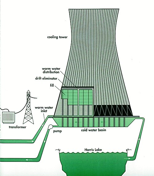
This photo shows a single natural draft cooling tower as used at a European plant. Natural draft towers are typically about 400 ft (120 m) high, depending on the differential pressure between the cold outside air and the hot humid air on the inside of the tower as the driving force. No fans are used.
Whether the natural or mechanical draft towers are used depends on climatic and operating requirement conditions.